“Can this printer fit the number of full-arch models my lab needs per build?”
For a dental laboratory, that is usually a more useful question than simply asking for the printer’s XYZ build volume.
The useful build capacity of a dental printer depends on the footprint and orientation of the models you actually print, not simply the printer’s advertised build-volume number.
A printer may have a large quoted build envelope, but that does not automatically mean it can accommodate the number of full-arch models, orthodontic models or working models required by your production schedule. The practical answer depends on model geometry, base design, orientation, supports, spacing, nesting strategy and the printable area the workflow can reliably use.
The American Dental Association also identifies build-platform size, product type, full- versus quadrant-arch printing, printing time and post-processing time as factors to consider when evaluating a dental 3D printer.
Build volume and build plate area are not the same thing
Build volume is normally expressed as three dimensions:
X × Y × Z
The X and Y dimensions describe the horizontal printing area, while Z describes the maximum available build height.
For example, Yidimu currently publishes a build volume of 223 × 126 × 290 mm for the Eternal D1 and 228 × 128 × 235 mm for the Eternal Y8. These specifications describe the available machine envelope, but they do not establish a fixed number of dental models per print job.
For routine dental model production, the X-Y area is often the first capacity constraint to examine.
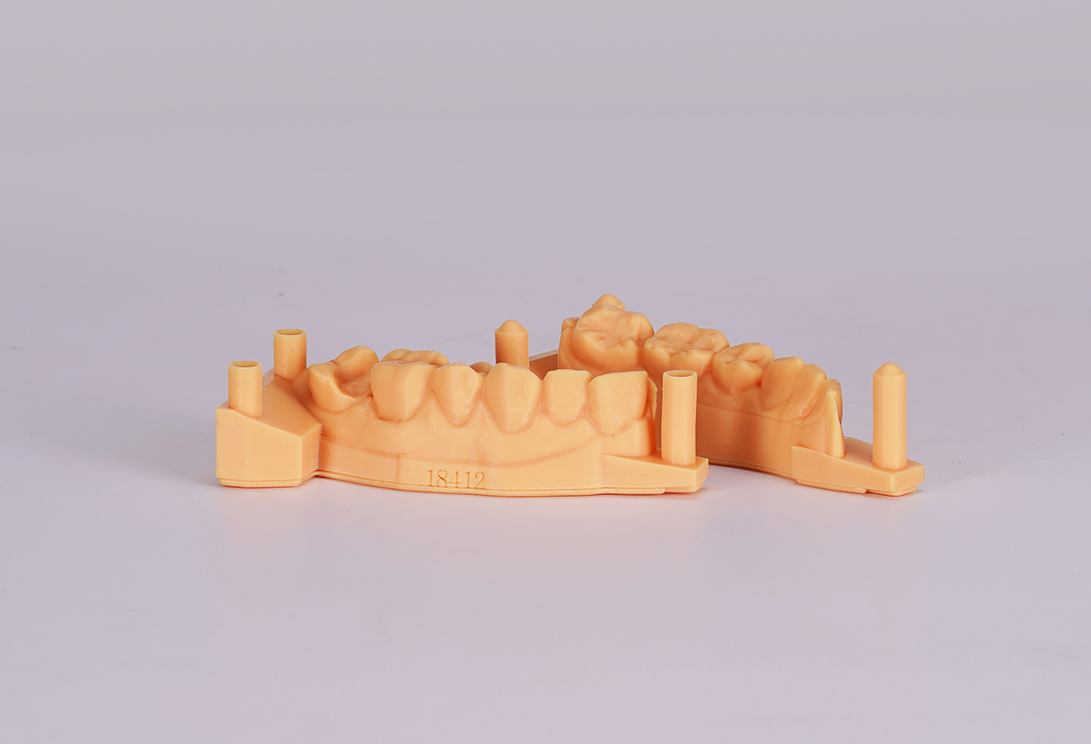
A full-arch model occupies a two-dimensional footprint when positioned on the platform. Several models must fit within the available printing area while leaving enough room for the selected orientation, supports, separation and any printer-specific restrictions.
The Z dimension matters too, particularly when models are tilted, supported or unusually tall. But a large Z height does not compensate for insufficient horizontal plate space when the goal is to print multiple dental arches in one build.
Think in terms of usable printable area
The physical dimensions of the platform are only the starting point.
What matters in production is the usable printable area.
A laboratory may choose not to place parts directly against every edge of the nominal build area. There may also be practical limitations related to support placement, resin behavior, platform calibration, slicing strategy or the validated printing process.
This means:
Nominal plate area ≠ automatically usable production area.
When evaluating capacity, create a realistic usable region in the slicing software and test models inside that region.
This approach is more meaningful than calculating plate area in square millimeters and dividing it by the surface area of a dental model.
Dental arches do not pack like rectangular boxes.
Their curved geometry leaves unused gaps, and those gaps change when the models are rotated.
Model footprint is the key measurement
Suppose two laboratories both print full-arch dental models.
Lab A uses compact horseshoe-shaped models with relatively narrow bases.
Lab B uses models with larger rectangular bases, additional geometry or different trimming rules.
Even if both laboratories use the same printer, their models may have very different platform capacity.
That is why the first practical measurement should be the footprint of a typical production model.
Do not measure only the original STL bounding box.
Measure or inspect the effective footprint after applying the orientation and support strategy that you would actually use for production.
The effective footprint may include:
- the model itself;
- the model base;
- support structures;
- raft or base structures where used;
- required clearance around neighboring parts.
A small change in orientation can significantly change how efficiently several arches fit onto a rectangular platform.
Full-arch models and quadrant models create different capacity problems
The phrase “dental model” covers very different geometries.
A full-arch working model can occupy a substantial part of the build plate.
A quadrant model may occupy much less space and may allow substantially denser nesting.
Orthodontic models can also vary depending on trimming, base thickness and whether upper and lower arches are arranged together.
Therefore, a claim such as:
“This printer prints X dental models at once”
is incomplete unless the manufacturer also defines exactly what kind of model was used and how it was arranged.
There is no globally valid number of dental models per build based only on build-plate dimensions.
Actual quantity depends on:
- model geometry;
- base design;
- model orientation;
- spacing;
- supports;
- software arrangement;
- printer restrictions;
- laboratory acceptance criteria.
Minidimu’s current Eternal Y8 documentation makes the same distinction, noting that actual model capacity depends on orientation, support placement, spacing, resin behavior and laboratory acceptance criteria.
Does build plate size matter for dental 3D printing?
Yes, but it matters in context.
A larger build plate can provide more opportunities to arrange multiple models, but only when the additional area can actually be used by the models you produce.
For example, extra platform width may be valuable if it allows another full arch to fit beside an existing row.
In another workflow, the same additional area might create little benefit because the model geometry cannot be packed efficiently into that space.
This is why comparing printers purely by total plate area can be misleading.
What matters is whether your real production files fit.
A better comparison is:
“How many accepted production models can I realistically arrange on this printer using my validated orientation and spacing?”
A practical way to calculate dental printer capacity
Rather than relying on a manufacturer’s generic model-count claim, laboratories can evaluate capacity using their own STL or OBJ files.
Step 1: Measure your typical model footprint
Select several representative files from routine production.
Include the types that account for most of your workload, such as:
- full-arch working models;
- orthodontic models;
- clear-aligner working models;
- quadrant models.
Prepare them using the orientation, base and support approach that would actually be used in production.
Record the effective X-Y footprint.
Do not choose only the smallest or easiest file.
Step 2: Estimate the usable plate area
Start with the printer’s published X-Y build dimensions.
Then determine what portion of that area your validated workflow will actually use.
If your process requires an edge margin, support clearance or another exclusion area, include it.
The goal is not to maximize theoretical coverage. It is to define a repeatable production layout.
Step 3: Test realistic orientation and spacing
Import several representative models into the intended slicing software.
Rotate and arrange them as they would be arranged in routine production.
Check for:
- overlapping model boundaries;
- overlapping supports;
- insufficient spacing;
- excessive footprint caused by orientation;
- unnecessary empty areas;
- models extending beyond the validated printable region.
This step is important because simple area division usually overestimates capacity.
A 20,000 mm² plate does not necessarily fit twice as many models as a 10,000 mm² plate. Packing efficiency depends on geometry.
Step 4: Calculate accepted models per build
After establishing a realistic layout, count only the models that can be printed using the laboratory’s accepted workflow.
A practical capacity metric is:
Accepted models per build = number of models that fit within the validated usable plate area using the required orientation, supports and spacing
Test more than one production file rather than relying on a single ideal model.
You may eventually record separate values for full arches, quadrants and orthodontic models.
That is much more useful than one generic “models per plate” number.
Step 5: Calculate daily production capacity
Models per build is still not daily capacity.
Daily usable output depends on the complete workflow.
Printing is followed by unloading, washing, drying, post-curing, support removal and inspection. Operator availability and failed or rejected builds also affect actual throughput.
Minidimu’s workflow documentation treats printing, washing, drying, curing and inspection as separate controlled stages rather than treating the printer as an isolated production step.
A useful planning model is:
Daily usable output =
accepted models per successful build
× successful builds completed per day
× usable yield
Do not calculate the number of possible builds per day using print time alone.
Consider:
- printing time;
- platform unloading and preparation;
- washing capacity;
- drying time;
- curing capacity;
- support removal;
- operator time;
- inspection;
- failed builds or rejected models.
Some processes can overlap. For example, one batch may be washing while the printer starts another build. For that reason, a dental lab should measure the actual workflow bottleneck rather than simply adding every process time together.
Why adding more models does not always multiply print time
There is another important production effect to understand.
In some mask- or projection-based vat-photopolymerization systems, an entire cross-section can be exposed as a layer at the same time. Research reviews of vat photopolymerization describe mask-projection systems as curing an entire layer cross-section in a single image exposure.
This means that adding another model within the same layer does not necessarily multiply exposure time in direct proportion to the number of models.
Four models on a platform do not automatically require four times the exposure duration of one model.
However, this should not be interpreted as “more models are free.”
Total cycle time can still be influenced by:
- the tallest model in the build;
- total layer count;
- layer thickness;
- exposure settings;
- lift, separation or repositioning movements;
- model cross-section and geometry;
- support strategy;
- resin behavior;
- the specific printer architecture and control strategy.
Vat-photopolymerization processes can include exposure followed by mechanical platform movement and resin renewal or repositioning between layers, so equipment architecture remains important when estimating total build time.
For this reason, laboratories should not assume a universal production speed from either model count or a manufacturer’s maximum speed specification.
Evaluate capacity using your own production mix
The right build volume for a dental lab is not necessarily the largest available.
It is the build area that fits the laboratory’s actual model mix with enough practical capacity to meet its production schedule.
Before selecting a printer, take several representative production files and ask:
Can the platform fit the required number of full arches?
How efficiently can upper and lower arches be nested?
What changes when quadrant models replace full arches?
Does the preferred support orientation reduce usable plate capacity?
How many accepted builds can the complete washing and curing workflow process in one working day?
What happens to daily output if one build fails?
These questions turn build volume from a specification-sheet number into a production metric.
For a dental laboratory comparing printers, the most useful test is therefore not simply:
“How big is the build volume?”
It is:
“Using our real files, validated orientation, spacing and post-processing workflow, how many usable models can this system reliably deliver per build and per working day?”
That is the number that matters for dental 3D printer capacity.